Floating Pins, Pull-Up Resistors and Arduino
Welcome to today’s tutorial, where we delve into the essential topic of ‘floating pins’ in Arduino. A ‘floating pin’ is a frequent concern in electronics, impacting the reliability of your circuits. This guide will provide a clear understanding of ‘floating pins’ and how implementing pull-up resistors can effectively address this issue, ensuring stable and precise Arduino projects.
Usually, one might think, if something’s floating, it’s a good thing. For instance, if a ship crashes, it floats in the ocean, and that’s better than sinking, right? However, with electronics, that’s not the case. Consider a hairdryer in the tub; that doesn’t mix well. The bottom line: floating pins are detrimental. This tutorial aims to explain why they are problematic and what precisely constitutes a floating pin.

Let’s establish a reference for this discussion. Sometimes, when working with Arduino, you may use digital inputs such as push buttons or sensors. These inputs typically have two states—on or off.
For example, a water detector indicates the presence or absence of water. You connect these sensors or buttons to a digital pin on the Arduino, and you use the digitalRead function to read the voltage from that pin and determine whether the pin is high or low. Let’s use a simple push-button circuit to understand this floating pin concept better. Connect an Arduino board on a breadboard with a push button. One side of the button connects to ground, and the other side connects to digital pin 2.
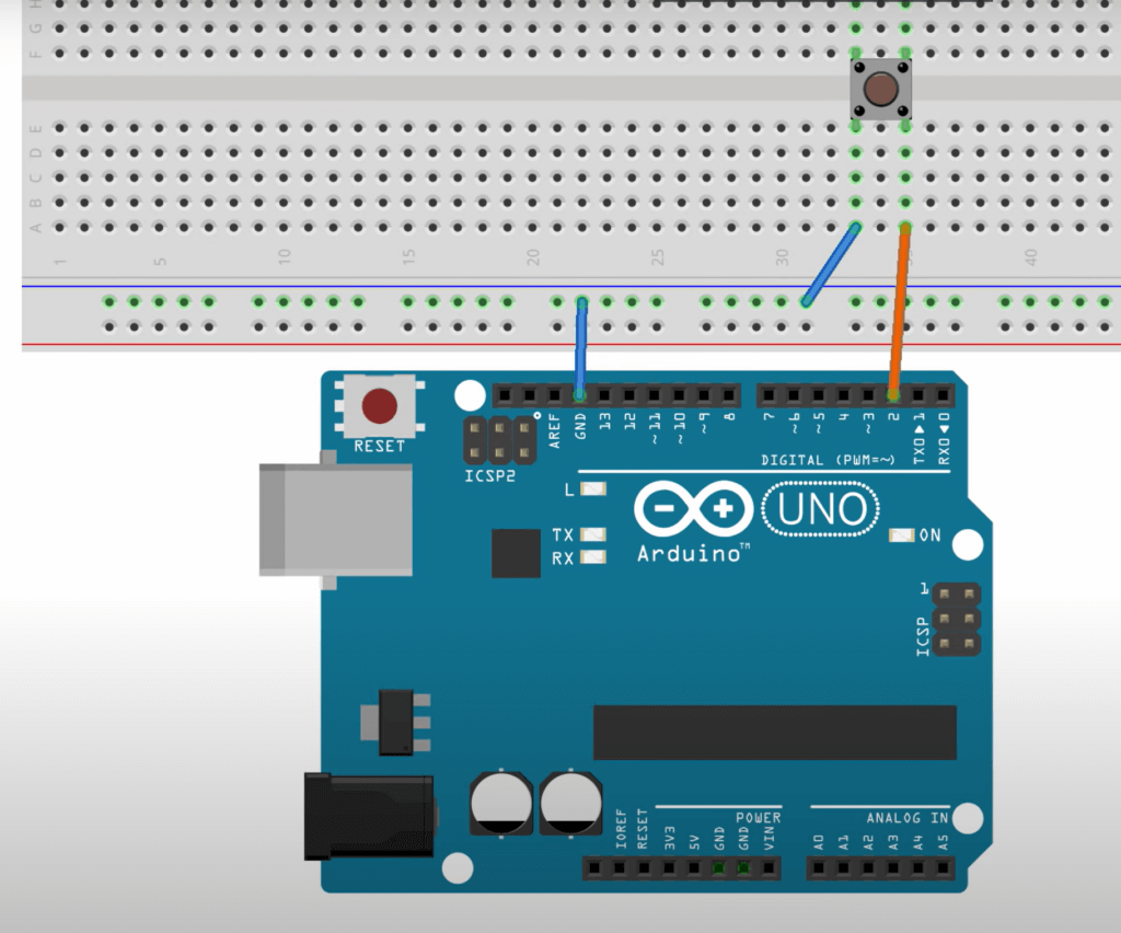
You monitor the voltage using the digitalRead function on digital pin 2. In this setup, when you press the button, digital pin 2 reads a low voltage (ground), and it returns a low value. In the program, you use an if statement to check if digital pin 2 is low and then proceed with the desired action, such as turning on an LED. However, the critical question is: what occurs at pin 2 when you’re not pressing the button? Let’s investigate this using the Arduino IDE.
Floating Pins – What the Serial Monitor shows
In the Arduino IDE, a simple sketch is created. First, pin 2 is designated as the input pin. Then, in the setup function, the mode of that pin is set as input, as discussed earlier, and serial communication is initiated. If some of this is unclear, you can refer to other resources for more details.
Now, let’s move on to the loop. First, a digitalRead is performed on that pin to determine its voltage. To do this, a variable named ‘sensorValue’ is declared and initialized to store the output of the digitalRead function, which will be either high (1) or low (0). Next, the serial print function is used to display this value on the serial monitor window.
//The input pin
int Pin_Input = 2;

void setup() {
  // put your setup code here, to run once:
  pinMode(Pin_Input, INPUT);

  Serial.begin(9600);

}  //close setup

void loop() {

  // read the voltage at the Input Pin
  int Sensor_Value = digitalRead(Pin_Input);

  //display the value at the sensor
  Serial.println(Sensor_Value);

}  // close loop
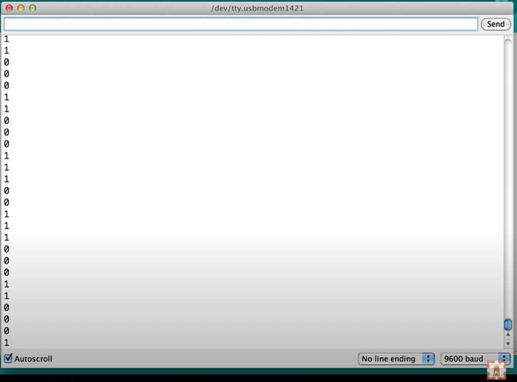
Now, observe the serial monitor; it displays ones and zeros in a seemingly random pattern. It appears as noise. Turning off auto-scroll allows for a closer examination. This demonstrates that pin 2 has no clear function when the button is not pressed; it’s in a floating state. Is this a problem? Does it matter? Yes, it does matter. Why? Let’s continue with the program and circuit setup to see how the LED performs.
Floating Pins – What the Serial Monitor shows
To incorporate an if-else statement into the code, let’s begin with an explanation. The if-statement checks whether the sensor value equals “low.” If it does, instruct the Arduino to set digital pin 13 to “high.” Most Arduino boards feature a built-in LED on pin 13. In this example, we use the Arduino UNO, which also has this LED. So, when the sensor value is low, the LED turns on. This may seem counterintuitive at first, but let’s recall the circuit: when the button presses, pin 2 connects to ground, resulting in a voltage of 0 volts. In digital terms, 0 volts represents “low.”
Now, lets delve into the code. Assign the sensor value based on the output of digital read. When you press the button, digital read returns a value of 0, setting sensor value to 0. Next, check if sensor value equals 0, indicating it’s low. If that’s the case, turn on the LED by setting digital pin 13 to “high.” If sensor value is anything else, turn it off.
So, the purpose becomes clear: pressing the button turns the light on, releasing it turns the light off. Before uploading the code, remember to set digital pin 13 as an output. Now, proceed with the upload.
//The input pin
int Pin_Input = 2;

void setup() {
  // put your setup code here, to run once:
  pinMode(Pin_Input, INPUT);

  Serial.begin(9600);

}  //close setup

void loop() {

  // read the voltage at the Input Pin
  int Sensor_Value = digitalRead(Pin_Input);

  //display the value at the sensor
  Serial.println(Sensor_Value);

  //if the button is pressed, turn the LED HIGH
  if (Sensor_Value == LOW) {

    digitalWrite(13, HIGH);


  } else {

    digitalWrite(13, LOW);

  }  //close if/else

}  // close loop
After uploading the code to the board, you may notice that the LED on pin 13 behaves strangely; it appears to pulsate or rapidly blink. This behavior is unexpected. Even when you don’t touch the button, the LED should not illuminate. However, pressing the button stops the pulsation, making the LED brighter. Releasing the button causes it to start pulsating again. What’s causing this?
To investigate further, return to the serial monitor. Unfortunately, the serial monitor displays the same erratic behavior, showing a stream of ones and zeros. The issue here lies with the “floating pin.” Regardless of pressing the button, noise interferes with the pin, causing an indeterminate value that incorrectly triggers button presses (resulting in a pulsating LED).
Eliminating floating pins with a Pull-up resistor
To resolve this issue, use a pull-up resistor. This component ties the floating pin to a known voltage, which in this case is 5V. Examine the revised breadboard layout, which includes an external pull-up resistor.
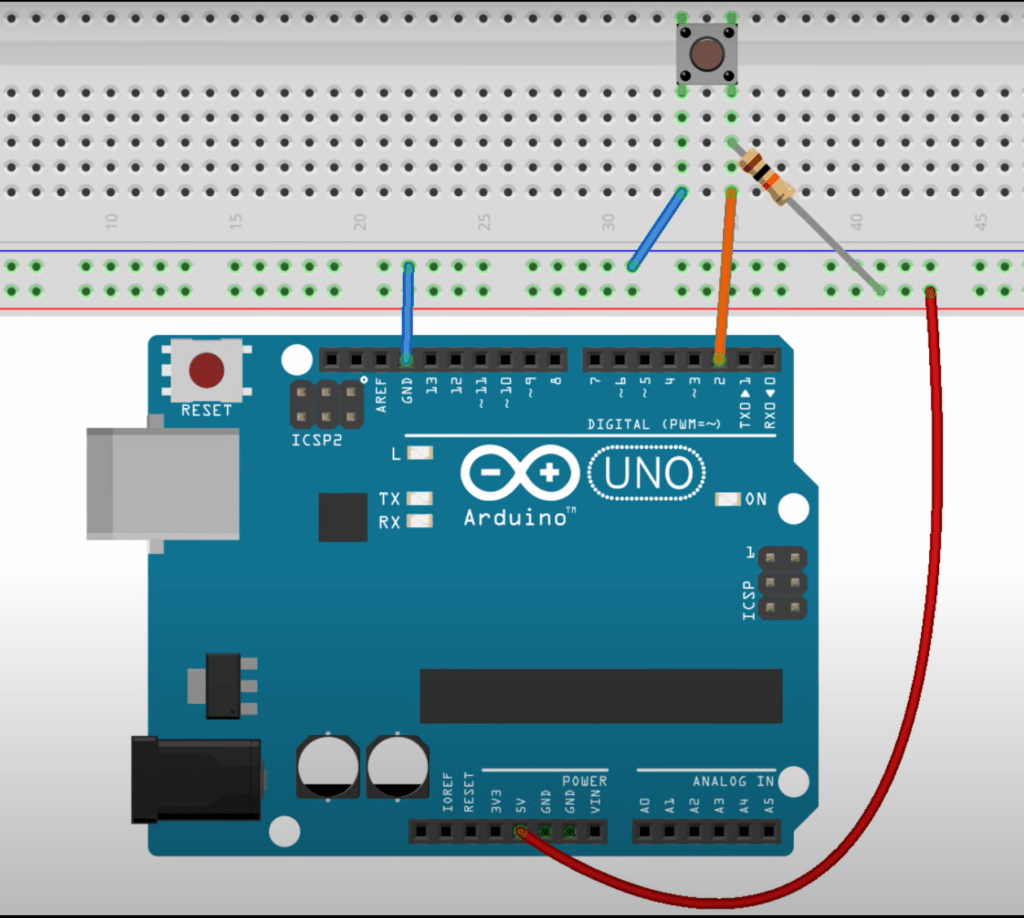
In addition to connecting the right side of the push button to pin 2, add a pull-up resistor connected to 5 volts. This resistor ensures that, when you’re not pressing the button, pin 2 reads a stable high signal, now connecting to 5V through the 10k resistor.
Returning to the Arduino IDE, you can see that the serial monitor consistently displays “1,” indicating that the pin is no longer floating. Pressing the button turns on the LED, and releasing it turns off the LED. This solution eliminates false button presses caused by a floating pin.
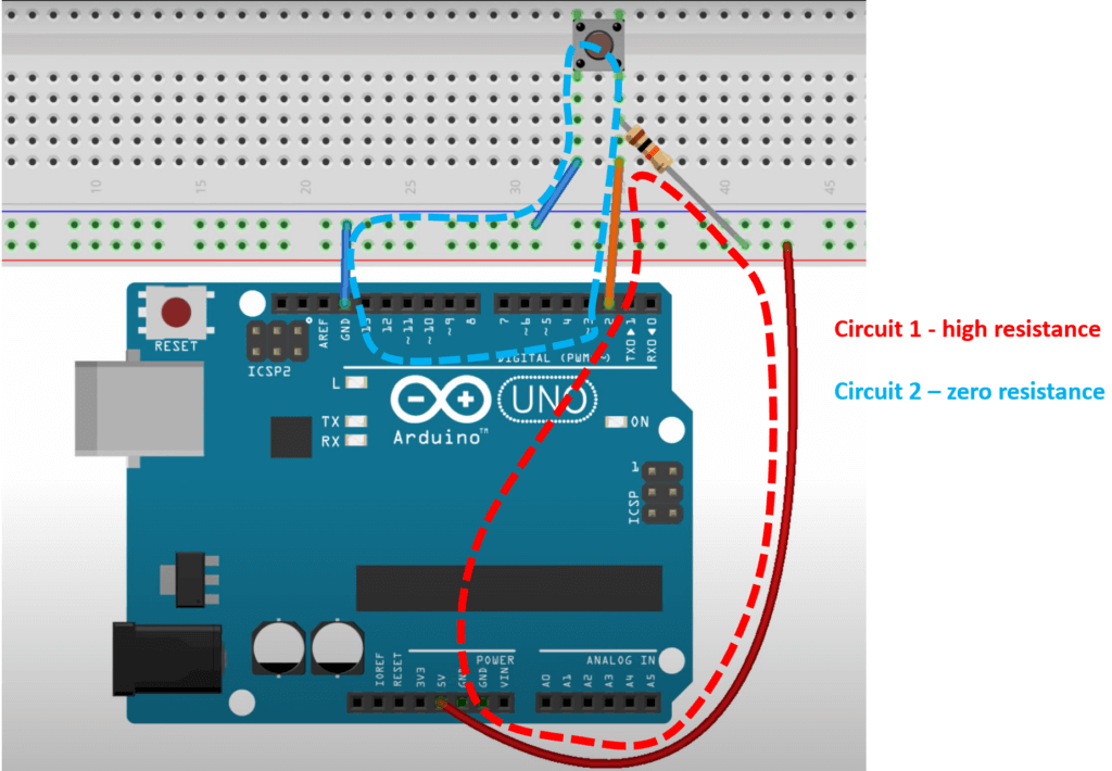
Let’s reiterate this main point: when you’re not pushing the button, the only closed circuit consists of the Uno’s 5V pin, the 10k resistor, and pin 2. This is why the serial monitor displays a ‘1.’ However, when you push the button, there are two potential closed circuits: the one mentioned earlier (with high resistance) and another one from ground, through the button, to pin 2 (with low resistance). This circuit has no resistance, and therefore it becomes the path of least resistance, and thus the serial monitor shows 0, and the LED turns on. Remember, given a choice, electrons will take the easiest way to complete a closed circuit, and will not do some arrangement of both.
Thank you for following this tutorial, we hope you found it helpful. Have a great day!
.
Great video. This was one of the first problems i had with arduino and i couldn’t understand why my circuits weren’t working. It was very frustrating and i think most users will have come across it, but no-one tells you about it. You just get resistors placed mysteriously in the examples, and once you step out on your own you get nowhere. So good on you.
Now i seem to remember i resolved by putting a resistor in the circuit in series with the button (in this example) which seemed to calm the noise. Could that be right?
All the best,
Lionel.
Thanks Lionel! A resistor pulling the Pin to ground would have definitely done the job!
As always enjoyed and help enforce things I may have known at one time. Using a Nano, did I read it has buildt in pull up/down resistors that can be called in the coding? If so, how?
Thanks
Hi Greg! That’s right, there is a way to use an internal PULLUP resistor on all the general purpose I/O (ie the digital pins, and the analog pins if used as digital pins). The code is simply pinMode(PIN#, INPUT_PULLUP) this sets an internal 20K pull up resistor.